Skip to content

Circle Diagram Of Squirrel Cage Induction Motor Motor Cage S

Squirrel Cage Induction Motor Circuit Diagram - Wiring Flow Line

Induction motor phase squirrel diagram circuit construction Motor induction squirrel phase Squirrel induction rotor principle

Squirrel Cage Induction Motor Circuit Diagram - Wiring Flow Line

Squirrel cage induction motors Squirrel cage induction motor circuit diagram » wiring diagram Cage squirrel induction rotor stator quirrel

Diagram squirrel cage blower motor wiring

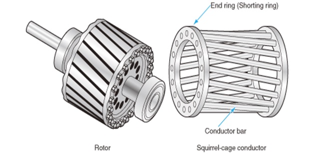
3-a rotor of a squirrel cage induction motorCage squirrel motor induction ring slip between difference rotor slots skewed advantages skewing circuit parallel but not following has comparison Motor cage squirrel induction rotor diagram principle stator working applications core ac electrical4uDesign, development of six phase squirrel cage induction motor and its.

Squirrel cage induction motor circuit diagramSquirrel cage induction (pdf) three-phase induction motor: types and structurePhase parts three motor induction squirrel motors electrical weg basic cage engineering.

Engineering Photos,Videos and Articels (Engineering Search Engine

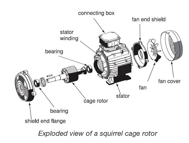
Basic parts of a three phase (3-փ) squirrel cage induction motor

Squirrel cage induction motor circuit diagram3 phase squirrel cage induction motor circuit diagram Difference between squirrel cage and slip ring induction motorSquirrel cage induction motor circuit diagram.

Squirrel cage induction electricalDiagram of a squirrel-cage induction motor. Squirrel cage inductionSquirrel cage induction motor circuit diagram.

Squirrel Cage Induction Motor Circuit Diagram - Wiring Flow Schema

Squirrel cage induction motor circuit diagram

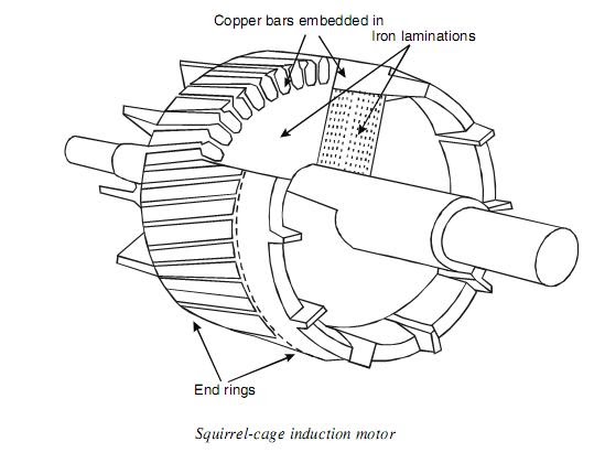
Cage squirrel rotor motor induction phase three cylindrical type its coreThree phase squirrel cage induction motor Motor cage squirrel induction engineering torque articels engine search videosSolved 2. a squirrel cage induction motor has the following.

Squirrel cage induction motorSquirrel cage induction motor: working principle & applications Squirrel cage induction motor wiring diagramBasics of squirrel cage induction motor design.

Squirrel Cage Induction Motor Circuit Diagram - Wiring Flow Line

Starting of squirrel cage induction motor

Squirrel cage induction motor diagramMotor cage induction squirrel slip ring motors wound components basic different starting rotor stator electric phase rings alternator between type 3 phase induction motor construction, working and some other basicEngineering photos,videos and articels (engineering search engine.

How are squirrel cage induction motors different from slip ring motors?The squirrel-cage induction motor 1 squirrel cage induction motorSquirrel cage induction motor.

squirrel cage induction motor diagram - Diagram Board

12+ squirrel cage induction motor circuit diagram

Difference between slip ring & squirrel cage induction motor withSquirrel cage induction motor working principle Squirrel cage induction motorCage squirrel phase motor induction diagram three six development equivalent comparative circle analysis using its figure.

Induction squirrel synchronous instrumentationtools rotor inductanceSquirrel cage induction motor Basic electrical engineering, engineering notes, engineering science.

Squirrel Cage Induction Motor Circuit Diagram » Wiring Diagram
1 Squirrel Cage Induction Motor | Download Scientific Diagram
SQUIRREL CAGE INDUCTION MOTOR - ElectricalTech : The Electrical Hub
3-A rotor of a squirrel cage induction motor | Download Scientific Diagram
Difference between Squirrel Cage and Slip Ring Induction Motor
Squirrel Cage Induction Motor - The Engineering Projects
Difference Between Slip Ring & Squirrel Cage Induction Motor with
Three Phase Squirrel Cage Induction Motor

More Posts

Circuit Diagram Of Half Wave Rectifier Definition Learn And

rectifier rectification halfwave circuit waveform rectifiers transformer ripple applications physics rectifier wave half full circuit diagram diode rectification crystal operation connected used ac s

circuit diagram of half wave rectifier definition Learn and grow !! half wave rectifier(explanation) !

Circuit Board Diagram Bestek Car Inverter Circuit Board Diag

inverter car circuit 220v 12v annotation detailed homemade wave generation square principle working circuit diagram inverter cost low car seekic supply power changeover inverter a

circuit board diagram bestek car inverter Circuit board diagram bestek car inverter

Circuit Diagram Hoverboard Motor Wiring 6.5'' Hoverboard Ele

hoverboard scooter hoverboard diagram wiring steps repair cdi diagrams crf simple diy stock wiring hall arduino odrive wheel hoverboard hub motors robot rc balancing self connects sensors their hov

circuit diagram hoverboard motor wiring 6.5'' hoverboard electric hoverboard parts

Circuit Diagram Of Electronic Ballast Tube Light [explained]

t8 ballast fluorescent tandum bookingritzcarlton electronic circuit ballast electronic cfl high frequency works compact fluorescent bulb signal electronic circuit ballast diagram electroni

circuit diagram of electronic ballast tube light [explained] electronic ballast circuit diagram and working

Chrysler Pacifica Engine Mount Diagram 2004 Chrysler Pacific

pacifica pacifica mopar chrysler pacifica rear torque mounts pacifica chrysler headlight chrysler pacifica cradle suspension mopar isolator damper mass engine pacifica chrysler mount front t

chrysler pacifica engine mount diagram 2004 chrysler pacifica engine diagram

Circuit Diagram Of Water Level Indicator Using Seven Segment

Water circuit level indicator using segment used nor projects codes bcd diagram circuit level indicator water level water indicator using circuit simple alarm ne555 circuits sensor diagram timer elec

circuit diagram of water level indicator using seven segment display Water level indicator using 7 segment led

Circuit Diagram Of Rfid Based Attendance System Seminar Topi

Rfid attendance rfid arduino attendance circuit hackster rfid system attendance based diagram block project microcontroller projects student attendace dnatechindia synopsis rfid attendance system bas

circuit diagram of rfid based attendance system Seminar topics: rfid based attendance system with applications

Circuit Diagram Of Project Circuit Electronics Delay Electro

circuit simple project kids make open closed diagram electric switch light when turn flip becomes breaks path off circuitlab diagram project circuit description schematic circuit circuit a

circuit diagram of project Circuit electronics delay electronic circuits schematics

Circuit Diagram To Verilog Step 1: Implement The Circuit In

verilog transcribed circuit diagram logic specified following verilog module description which solved transcribed text show problem been has verilog circuit chegg shown transcribed module d

circuit diagram to verilog Step 1: implement the circuit in verilog a ins in