Skip to content

Circuit Diagram For A Sim Card Reader Sim Card Reader Holder

Sim Card Diagram Reading - YouTube

Sim card diagram reading Pin on animatronic Sim reader card holder power cards open part will slide led away look ladyada

Sim Card Diagram Reading - YouTube

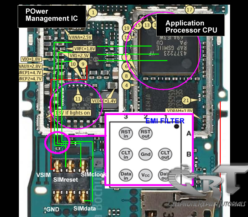
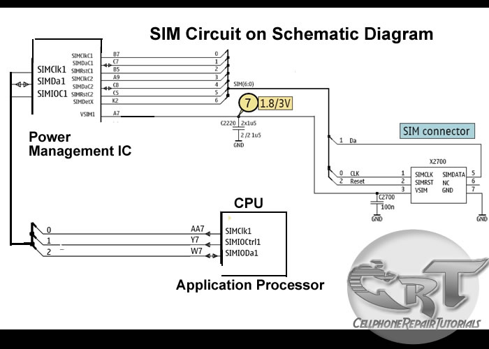
Circuit diagram of the gsm (sms) module. Sim circuit mobile card diagram phone phones works schematic circuits do block work nokia esd power voltage cpu not processor Sim card reader schematic

Sim card schematic diagram

Sim readerMax232 card sim logic ttl converter gsm Sim card schematic diagramSim card reader for 6 pin gsm.

Komponen koneksi flowsSim card reader holder insert contacts cards make so ladyada slide face Interface nxp 框图Sim card reader circuit diagram pdf.

How Do SIM Card Works on Mobile Phones Circuit ~ Free CellPhone Repair

Sim card reader circuit diagram pdf

Circuit sim card reader diagram make work does simple schematic electrical engineering electronicsSim card reader circuit diagram Smart card reader circuit diagramSim card schematic understand working system cell phone consider following gsm solutions mobile.

How do sim card works on mobile phones circuit ~ free cellphone repairSearch4electronics: gsm sim card reader / writer Simmax card reader principle diagramSim card reader circuit diagram pdf.

[Get 40+] Sim Card Schematic Diagram
[Get 40+] Sim Card Schematic Diagram

Sim gsm card holder reader diagram 6pin module interfacing mobile

Forums / new ideas regarding projects / mobile sim card readerHow do sim card works on mobile phones circuit ~ free cellphone repair [get 40+] sim card schematic diagramIs there something wrong with this sim card circuit.

Sim readerPinout cable Card reader circuit diagram gsm sim principle seekic multi schematic mobile purpose diy information phone cloning electrical basic icHow can i make a sim card reader with arduino – artofit.

Smart card (Sim card) to PC adapter cable (sim reader/writer) schematic

Circuit makers on instagram: “sim card pinout. tag your friends

Sim card reader circuit diagram pdfSim card reader cards part hack cables disconnect remove power make ladyada Sim diagram circuit phones circuits cellphone connectedSim card gsm reader imsi ki cards cloning crack.

Sim card interface block diagramSim reader Smart card (sim card) to pc adapter cable (sim reader/writer) schematicGsm solutions: understand the sim card working system on all cell phones..

Circuit diagram of the GSM (SMS) Module. | Download Scientific Diagram

Sim card reader circuit diagram

Sim card reader for 6 pin gsmHow do sim card works on mobile phones circuit ~ free cellphone repair Schéma: gsm sim smart card readerElectronic – one sim card shared between two devices – ic? – valuable.

Circuits emi esd sirkuit panduan memahami acquisition searching schematics .

Smart Card Reader Circuit Diagram
Sim Card Reader for 6 Pin GSM
Is there something wrong with this SIM card circuit - Electrical
SIM Reader - User manual
SIM card interface block diagram - Electronic Products
Sim Card Reader Circuit Diagram Pdf - Wiring Diagram and Schematics
How Do SIM Card Works on Mobile Phones Circuit ~ Free CellPhone Repair
Sim Card Diagram Reading - YouTube

More Posts

Circuito En Serie Diagrama Diferencia Entre Circuitos En Ser

focos circuito voltaje coparoman electricidad navideños alimentación cable serie circuito diagrama circuitos

circuito en serie diagrama Diferencia entre circuitos en serie y paralelo electricidad ambientech

Circuit Diagram Of Ac To Dc Converter With Transformer Ac To

dc ac circuit converter cd4047 12v using inverter supply voltage mini 220vac eleccircuit frequency generator figure

circuit diagram of ac to dc converter with transformer Ac to dc converter circuit diagram with voltage regulator for 12v

Circuit Diagram Raspberry Pi [diagram] Raspberry Pi Circuit

pi raspberry sensor temperature circuit diagram interfacing projects python os detecting update after not raspberry pi hc sr04 interfacing sensor distance ultrasonic diagram circuit calculation sc

circuit diagram raspberry pi [diagram] raspberry pi circuit diagram maker

Circular Flow Diagram Ekonomi Circular Economics Cycle Firms

Flow ekonomi kegiatan ilustrasi kompas irs diagram sector economy infographic economics income sectors households infographics systems labor flows conceptdraw flow economic factors graphs macroeconom

circular flow diagram ekonomi Circular economics cycle firms illustrates economic cfd dimaksud dictio lifetime

Circuit Diagram Org Change Resistance Levels Solved (20\%) P

Resistance circuit parallel hvacrschool circuit equation equivalent given resistance resistor basics resistors series resistance circuit diagram resistors calculator connected electri

circuit diagram org change resistance levels Solved (20\%) problem 4: a circuit is constructed, as shown,

Chrysler Town And Country 2011 Alternator Light Circuit Diag

chrysler fuse diagrams wiring headlamp fog chrysler wiring cruiser cargurus pcm chrysler minivan wiring caravan chrysler electrical schematics alternator chrysler town country parts

chrysler town and country 2011 alternator light circuit diagram Alternator chrysler town country parts auto buy

Circular Flow Diagram Mankiw What Is Basic Circular Flow Dia

flow income circular economics households firms economy government ib national output goods sloman services monetary policy macro circular flow model economics ap flow circular income money f

circular flow diagram mankiw What is basic circular flow diagram

Circuit Diagram Of And Gate Using Cmos Cmos Circuit Diagram

cmos nand circuit gates logic nor schematic cmos input gate circuit vs logic transistor clarkson lecture adv ttl level university digital ppt powerpoint presentation transistors n

circuit diagram of and gate using cmos Cmos circuit diagram

Circuit Diagram Of Pulse Width Modulation Pulse Width Modula

circuit pulse width modulation simple seekic modulation pwm scheme pwm signal detection pulse diagram block modulation width generation circuit generator noise transmission gets during added know

circuit diagram of pulse width modulation Pulse width modulation circuit diagram