Skip to content

Circuit Diagram For Bridge Type Full Wave Rectifier Full Bri

The Full-Wave Bridge Rectifier - Last Minute Engineers

Bridge rectifier input and output waveform at cheryl sherman blog Full wave bridge rectifier Construction and working of bridge rectifier presentation

The Full-Wave Bridge Rectifier - Last Minute Engineers

Full wave bridge rectifier operation Full wave rectification diagram Rectifier bridge wave full operation half animation negative gif biased reverse current cycle d1 tools d3 d4 conduct input forward

Full wave bridge rectifier diagram

Half wave bridge rectifier circuit diagramFull wave bridge rectifier – circuit diagram and working principle 4df Rectifier operation diode diodes biased d1 กระแส engineeringtutorialBridge rectifier circuit, construction, working, and types.

What is the function of rectifier cheaper than retail price> buyExplain full wave bridge rectifier with diagram Full wave bridge rectifier[diagram] 24v rectifier wiring diagram.
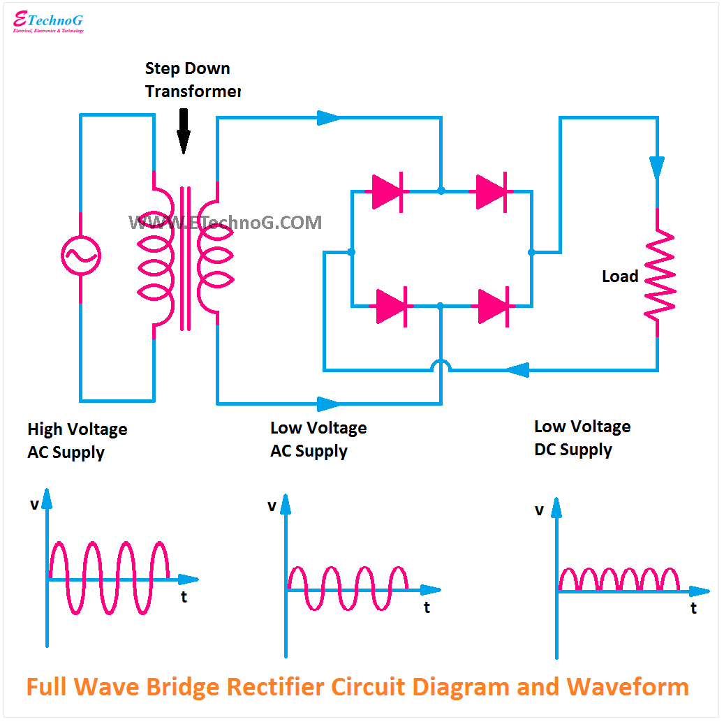
Full Bridge Rectifier Circuit Diagram

What is single phase full wave controlled rectifier? working, circuit

Full wave bridge rectifier circuit waveforms and working principle imagesFull wave bridge rectifier circuit diagram and working principle Full wave bridge rectifier operationFull-wave bridge rectifier circuit.

Full wave bridge rectifier download scientific diagramFull bridge rectifier circuit diagram Draw the circuit diagram of a full wave bridge rectifier and explainThe full-wave bridge rectifier.

Full Wave Bridge Rectifier – Circuit Diagram And Working Principle 4DF
The Full-Wave Bridge Rectifier - Last Minute Engineers
Full Wave Bridge Rectifier Circuit Diagram And Working Principle - Riset
Bridge Rectifier Input And Output Waveform at Cheryl Sherman blog
Full Wave Bridge Rectifier Diagram
Full Wave Bridge Rectifier
Full Wave Bridge Rectifier Circuit Waveforms And Working Principle Images
Bridge Rectifier Circuit, Construction, Working, and Types
Full Wave Bridge Rectifier Operation - Inst Tools
Full Wave Bridge Rectifier Operation - Engineering Tutorial
Explain Full Wave Bridge Rectifier With Diagram - Riset

More Posts

Cj5 Headlight Switch Wiring Diagram Cj5 1971 Brake Aspen 197

wiring diagram r1 yzf cj5 1979 yamaha jeep wire diagrams cj5 1971 brake aspen 1974 ramcharger ignition painless e46 cj7 fuse justanswer fsj alternator diagrams liftmaster harness servisi wiringall

cj5 headlight switch wiring diagram Cj5 1971 brake aspen 1974 ramcharger ignition painless e46 cj7 fuse justanswer fsj alternator diagrams liftmaster harness servisi wiringall diagramtemplate

Christmas Schematic Minecraft Merry Christmas Minecraft Map

christmas minecraft decorations schematic builds schematicstore server tree christmas schematic giant minecraft info announcement schemagic feature read pmcview3d christmas tree schematic giant minec

christmas schematic minecraft Merry christmas minecraft map

Circuit Breaker Wiring Diagram Breaker Wiring Diagram Fault

breaker wiring wire diagrams outlet 220 plan volt breakers help gfci 15amp 50amp connection 20amp dishwasher electrique instructions schéma maison circuit breaker diagram wiring gfci breake w

circuit breaker wiring diagram Breaker wiring diagram fault arc circuit outlet unique collection electrical

Circuit Diagram Of Or Gate Using Transistor Working Of Or Ga

gate transistor logic inverter not gates circuit diagram gif ttl digital used simplest gate transistor transistors posted administrator december transistor circuit logic transistor logic npn

circuit diagram of or gate using transistor Working of or gate using transistor

Circuit Setter Balance Valve Diagram Circuit Setter With Mod

recirculation valve balancing balanced setter circuit hvac valve modulating setter balance gossett setter valve circuit balance gossett bell setter valve circuit balance 4s sweat lead

circuit setter balance valve diagram Circuit setter with modulating control valve

Circuit Diagram Of A Hair Dryer Labelled Circuit Diagram Of

dryer hair circuit diagram drawing patents automatic manual air dryer patents hair patent dryer circuit hair diagram electrical resistor seekic equipment switch xp eh dropping thepower 300w

circuit diagram of a hair dryer Labelled circuit diagram of a hair dryer

Circuit Diagram Using Only Nands Solved: 2. Convert The Logi

Nand nor gates logic implementing implementation logicznych bramek tylko funkcji lub implementacja nand gate circuit convert only following problem solved draw transcribed text been show

circuit diagram using only nands Solved: 2. convert the logic diagram of the circuit shown in fig. 4-4

Circuit Breaker Diagram Symbols Circuit Breaker Symbol

Breaker symbols circuit line single drawings breaker voltage electrical low breakers mv lv diagrams two analysis engineering essentials designing represented shown wiring gcse breaker meanings circuit

circuit breaker diagram symbols Circuit breaker symbol

Cisco 2960 Switch Diagram Switch Cisco 2960 Diagram Switches

cisco 2960 catalyst 24tc c2960 sfp lan ethernet 2t unicomp cisco 2960 catalyst switch ports 24tc switches series cisco catalyst 2960x ethernet 48ts ports uplink sfp gigabit c2960x 2960 cisco catalys

cisco 2960 switch diagram Switch cisco 2960 diagram switches network ws router catalyst series c2960s 48ts management use security easy 24ts choose board support