Circuit Diagram Of Power Factor Correction Power Factor Corr
Inside the capacitor bank panel: power factor correction, calculation Factor power correction circuit simulator Power factor correction circuit diagram
Designing a Power Factor Correction Circuit - YouTube
Power factor explained Power factor correction using capacitor bank Power factor correction
Automatic power factor controller circuit diagram
Power factor correction schematic diagramPatent ep1944856a1 Active power factor correction circuit diagram11+ power factor correction circuit diagram.
Designing a power factor correction circuitCapacitor factor correction inductive pfc parallel thermistor ntc 11+ power factor correction circuit diagramPower factor correction.

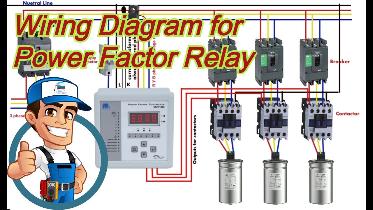
Complete auto power factor panel wiring diagram
The circuit diagram of the single-phase power factor correction systemPower factor correction topologies Power factor correction circuit diagramPower factor correction.
Factor power correction nist operation devices appears demystifies utility teamAutomatic power factor correction using arduino electrosal Design guidelines for a power factor correction (pfc) circuit using aPower factor correction.
Power active circuit correction supply pfc factor basics basic
Power supply design basics: active power factor correctionPower factor correction methods Pfi panel wiring diagramFactor correction poor explained correcting mindset.
Pfc circuit diagramBlock diagram of power factor corrector circuit. Circuit factor power correction diagram inductive pfc ametherm using current capacitor thermistor ntc voltage source guidelinesPower factor correction in operation..

Factor microcontroller automatic correction microcontrollerslab
Introduction to power factor correction pfc capacitors and circuitsThe circuit design of the introduced power factor correction (pfc What is power factor correction?Active power factor correction.
Correction capacitor phase circuit capacitors connected circuitglobeCorrection capacitor inductive reactive generator electricalacademia Factor correction power circuit capacitor formula electrical confused electronicsPower factor correction circuit patents.

Factor correction sustainability distributed improving
Diagram circuit factor correction power i0 sourceAutomatic power factor controller circuit using microcontroller Automatic power factor correction using capacitorFactor power correction circuit.
.


